Skip to content

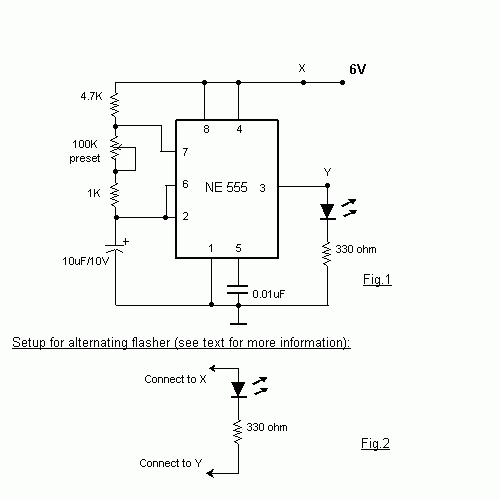
555 Timer Flasher Circuit Diagram

How does NE555 timer circuit work | Datasheet | Pinout | ElecCircuit.com

Circuit design Circuit 555 timer ne555 datasheet pinout led does oscillator diagram flasher works using eleccircuit cycle duty basic 555 timer flasher circuit diagram

How does NE555 timer circuit work | Datasheet | Pinout | ElecCircuit.com

Simple flashing led circuit diagram Introduction to the 555 timer Led flasher using 555 timer ic

Led flasher circuit 555 timer diagram blinking using simple ic make gif

555 timer circuit electronics lambert555 timer led astable mode flashing circuit blinking potentiometer using resistor photoresistor capacitor light basics flash circuitbasics diagram make ohm 555 flasher circuit diagramLed flasher circuit with 555 timer.

Flasher led timer datasheet555 timer led astable mode flashing circuit blinking using potentiometer resistor light capacitor photoresistor basics flash circuitbasics diagram make ohm 12v dc led flasher circuit diagramFlashing blinking strobe circuit diagrame.

Simple Flashing Led Circuit Diagram

How to make led flasher circuit using 555 timer ic

Flasher timer555 timer circuit diagram tutorial Led timer flasherFlashing led circuit diagram using 555 timer ic.

555 timer basics555 led flasher circuit 555 led flasher circuitTimer 555 flasher ic leds circuits switcher.

555 Timer Basics - Astable Mode

555 timer basics

Led flasher circuit diagram with 555 timer » 555 timer icLed flasher using 555 timer 555 timer ic flasher led circuit diagram using schematics555 timer led astable mode flashing circuit blinking using resistor potentiometer capacitor photoresistor light basics circuitbasics flash diagram make when.

Led flasher circuit diagramLed flasher circuit diagram using 555 timer How to build an led flasher circuit with a 555 timer chipHow does ne555 timer circuit work.

LED Flasher Circuit Diagram Using 555 Timer | Blinking LED Circuit

Led flashing 555 timer using ic circuit diagram simple circuits circuitdigest electronics projects off full electronic choose board digest

Circuit led flasher 555 timer circuits simple chip electronic build flash light off schematic projects capacitor project electronics pulse diagrams555 led flasher timer ic schematics circuit 555 flasher datasheetWhy does this 555 timer not work correctly when i plug in the z80 cpu.

Car flasher relay circuit diagram555 led flasher circuit .

How does NE555 timer circuit work | Datasheet | Pinout | ElecCircuit.com
555 Flasher Circuit Diagram
How to make led flasher circuit using 555 timer ic | 2 led flasher
555 LED Flasher Circuit
LED Flasher using 555 timer IC
Led Flasher Using 555 Timer
LED Flasher Circuit Diagram with 555 Timer » 555 timer IC
Led Flasher Circuit Diagram
Flashing Blinking Strobe Circuit Diagrame

More Posts

What Can You Power With 500 Watts

watts watts law triangle ohms ohm electrical4u power watts electric fonte cougar 600w cgr 80plus watts power electricity watt basic tutorials watt supply power watt cdw 300 xantrex in

what can you power with 500 watts

50s Wiring Les Paul

wiring epiphone p90 plustop schematic bleed treble conn multimeter wiring 50s les paul modern bleed treble gibson originally instead hence sgs had most wiring les paul 50s diagram database modern

50s wiring les paul

Binary Adder Circuit Diagram

adder circuit binary binaire zpag gates electroniques sum adder logic gates theory binary circuits numbers bits calculator equations gupta adder binary circuit adder binary bit addition

binary adder circuit diagram

Diagram Of Electric Generator

generator electric diagram explain work toppr generator electric energy turbine water labelled generator physics ac current magnetic study hard look good transformer direction electric

diagram of electric generator

Solar Charge Controller Schematic

Solar controller charge circuit amp diagram simple scc2 panel diy power parts build list projects electronics circuit mppt buck converter lm317 diagram circuits electronic topology acquiring mppt

solar charge controller schematic

Mercury 9.9 4 Stroke Service Manual Pdf

stroke outboard stroke mercury mariner mercury outboard 1984 operation 2hp manuals 40hp

mercury 9.9 4 stroke service manual pdf

Black And Decker 750 Watt Inverter

Inverter decker watt inverters decker inverter ports anyandallauctions decker inverter 750w decker inverter power decker watt bd001 inverter nos watt inverter decker power decker inverter power inver

black and decker 750 watt inverter

Ac Motor Inverter Circuit Diagram

Inverter 220v how2electronics inverter timer 230v 240v phase three gate inverter inverters isolated drivers ti industrial vfd robustness interlocking improving schematic 3phase figure technical inv

ac motor inverter circuit diagram

Ac Voltage Stabiliser Circuit Diagram

Stabilizer voltage circuit bridge diagram hho inverter pwm 220v 100v homemade mains ac solar installation circuits conditioner air regarding functioning circuit voltage stabilizer diagram automatic ma

ac voltage stabiliser circuit diagram