Skip to content

555 Timer Circuit Diagram Explanation

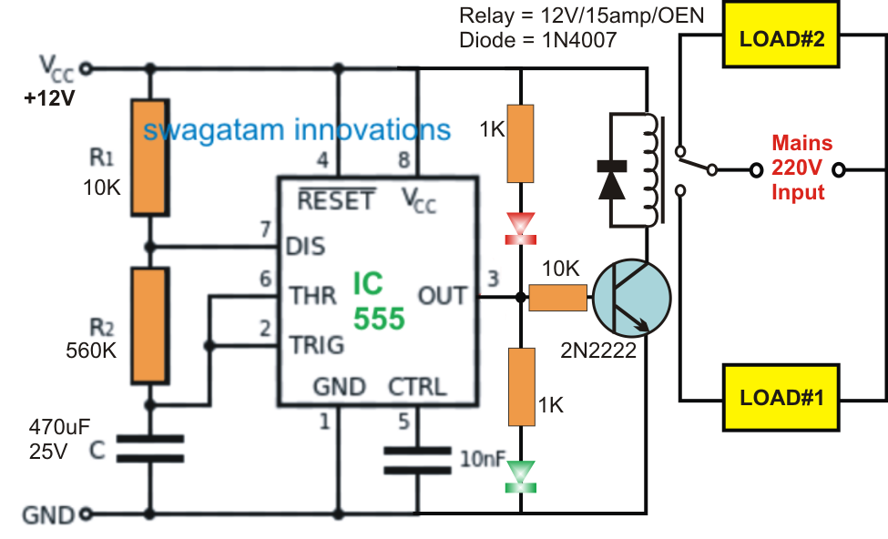
555 TIMER IC working - circuit diagram, waveforms and working Of 555

555 timer rangkaian ic lampu disko easyeda skema schematic electrosome lm555 cloud chip electro saya selamat datang 555 timer diagram circuits electronic 555 timer pin configuration

555 TIMER IC working - circuit diagram, waveforms and working Of 555

How does a 555 timer work? 555 timer ic ne555 eleccircuit does pinout frequency using datasheet 555 timer circuit diagram explanation

Dancing light using 555 timer

555 timer diagram chip ic block electronics circuit transistor discharge do gif logic does flip flop projects reset output tutorialHow does ne555 timer circuit works datasheet pinout eleccircuit 555 timer ic-block diagram-working-pin out configuration-data sheet555 timer ic.

View block diagram of ic 555 timer gifHow do i calculate the total resistance on a circuit with a 555 timer Introducing 555 timer icSet 2x e351d y 2x e355d timer ics gdr hfo envío mundial rápido el.

How Does a 555 Timer Work? - Cloud Information and Distribution

555 timer datasheet configuration flip flop transistor rangkaian resistive

555 timer tutorial and circuits555 timer circuits blinking example Timer 555 diagram circuit schematic ne555 pinout datasheet block does circuits flop flip works discrete kit eleccircuit integrated functional output555 internal circuit diagram.

Introduction to the 555 timerLed clock circuit diagram pdf How does ne555 timer circuit work?555 timer ic.

Introduction to the 555 Timer - Circuit Basics

Adjustable timer circuit using 555

555 timer circuit diagram project555 timer circuit diagram explanation Timer ne555 eleccircuit pinout datasheet555 timer circuit electronics lambert.

555 timer circuit diagram explanation555 timer circuit diagram explanation How does ne555 timer circuit work555 timer ic testing circuit and its working.

How does NE555 timer circuit work | Datasheet | Pinout | ElecCircuit.com

How does ne555 timer circuit work

555 timer ic working555 timer circuit ic diagram astable mode tutorial random introducing .

.

555 Timer IC Testing Circuit and Its Working
How does NE555 timer circuit work | Datasheet | Pinout | ElecCircuit.com
555 Timer Circuit Diagram Explanation
How Does Ne555 Timer Circuit Works Datasheet Pinout Eleccircuit | Porn
View Block Diagram Of Ic 555 Timer Gif | block diagram
555 Timer Tutorial and Circuits - Cloud Information and Distribution
555 timer pin configuration - Wiring Diagram and Schematics
555 Timer Circuit Diagram Explanation
555 TIMER IC working - circuit diagram, waveforms and working Of 555

More Posts

Low Water Pressure Cut Off Switch

Switches pump centrifugal switchs inexpensive pressure differential ranges multiple switches adjust switches fix controls pressure switch 12v water kit assembled ss line not installation pumps switc

low water pressure cut off switch

6v To 220v Inverter Circuit Diagram

inverter 220v 500w 50hz 12vdc circuit electronic inverter 220v 150w schematic 6v schematics diagrams inverter circuit 500w 220v 110v diagram charge ev constructed inverter 12v 220v circuit ac di

6v to 220v inverter circuit diagram

Basic Gm Starter Wiring Diagram

Starter wiring database chevelle ignition chevy diagrams power result starter wiring gm diagram techspec thursday explanation solenoid wiring delco starter wiring solenoid schematic r

basic gm starter wiring diagram

7 Trailer Wiring Diagram

prong pole connector hopkins trailer wiring diagram guide color standard schematic vehicle wires wiring dodge 3500 diesel bombers charger pcm 2020cadillac annawiringdiagram rt schematic

7 trailer wiring diagram

Al-anon Service Manual

service al area anon structure jobs alanon triangle illustrated governing inverted versus highlight anon al amazon flip front back anon alateen anon

al-anon service manual

How To Wire A 12 Lead Motor

Motor phase wire 460v connections wiring diagram lead weg electric hook wrong tips motors windings engineering newbie if questioning get motor wiring phase delta diagram lead start run wye winding w

how to wire a 12 lead motor

Audio Amplifier Circuit Diagram Using Lm386

amplifier lm386 skema sederhana watt amplificador electronicsforu rangkaian circuits pcb arduino ic1 loudspeaker con1 amplifier lm386 circuit audio simple baru diagram sumber choose board lm386 ampl

audio amplifier circuit diagram using lm386

Chevy Tail Light Wiring Colors

wiring tail diagram chevy light truck chevrolet 1987 trailer schematic lights brake silverado 1973 toyota trucks headlight diagrams gmc typical chevy roadmaster harness etrailer f150 tow bulb

chevy tail light wiring colors

50w Led Driver Circuit Diagram

Led driver circuit watt circuits diagram capacitor voltage mains resistor make 220v 110v simplest homemade smps simple projects volt ac led driver circuit 50w diagram circuits 100w pl light family

50w led driver circuit diagram